SmartLights
Motion activated lighting with solar charged battery power
Some time ago Jeff Crews built and installed a "Little Free Library" at the Scrap Exchange in Durham. There was talk of arranging solar power for it but the multiple watt consumption of the WIFI access point included in the library for download of free media such as audio books put us off and the plan was changed to simply running power from the Scrap's main building to the library. That didn't happen and instead the WIFI access point was moved indoors.
Then it became clear there was a need for lighting for people to see the book titles inside the library during evening hours. After he constructed the library Jeff Crews added strips of LED lights that can provide excellent light levels, but at about 1.1 amps at 12 volts. It may still turn out to be easiest for the long term to run 12 volts DC through a durable underground cable from indoors, but in the meantime I was approached to create a solar powered lighting system to run the LED strips. The rest of this is about a project aimed at lighting the library while also making progress with several personal goals that I'd been pursuing for some time already.
So this project is to satisfy two sets of goals:
- Causing the inside of the Little Library to be well lit for short intervals during night time hours, either when the library doors are opened, when someone approaches it, or some combination of the two. At least an hour of full brightness light should be available every night during sunny weather, doled out a half a minute here, five minutes there in typical conditions. A shorter total duration or lower brightness will be used to compensate for actual use patterns with actual weather (i.e. the amount of sunshine).
- Learning about solar energy, maximum power point tracking (MPPT) battery chargers, both off the shelf and custom designs, and a few related areas like thermistor usage for float voltage adjustment, how well TCO clock chips actually work with extreme temperature swings, and efficient cooling among others. The design described below is very much more complex and capable than it would be without this second set of goals.
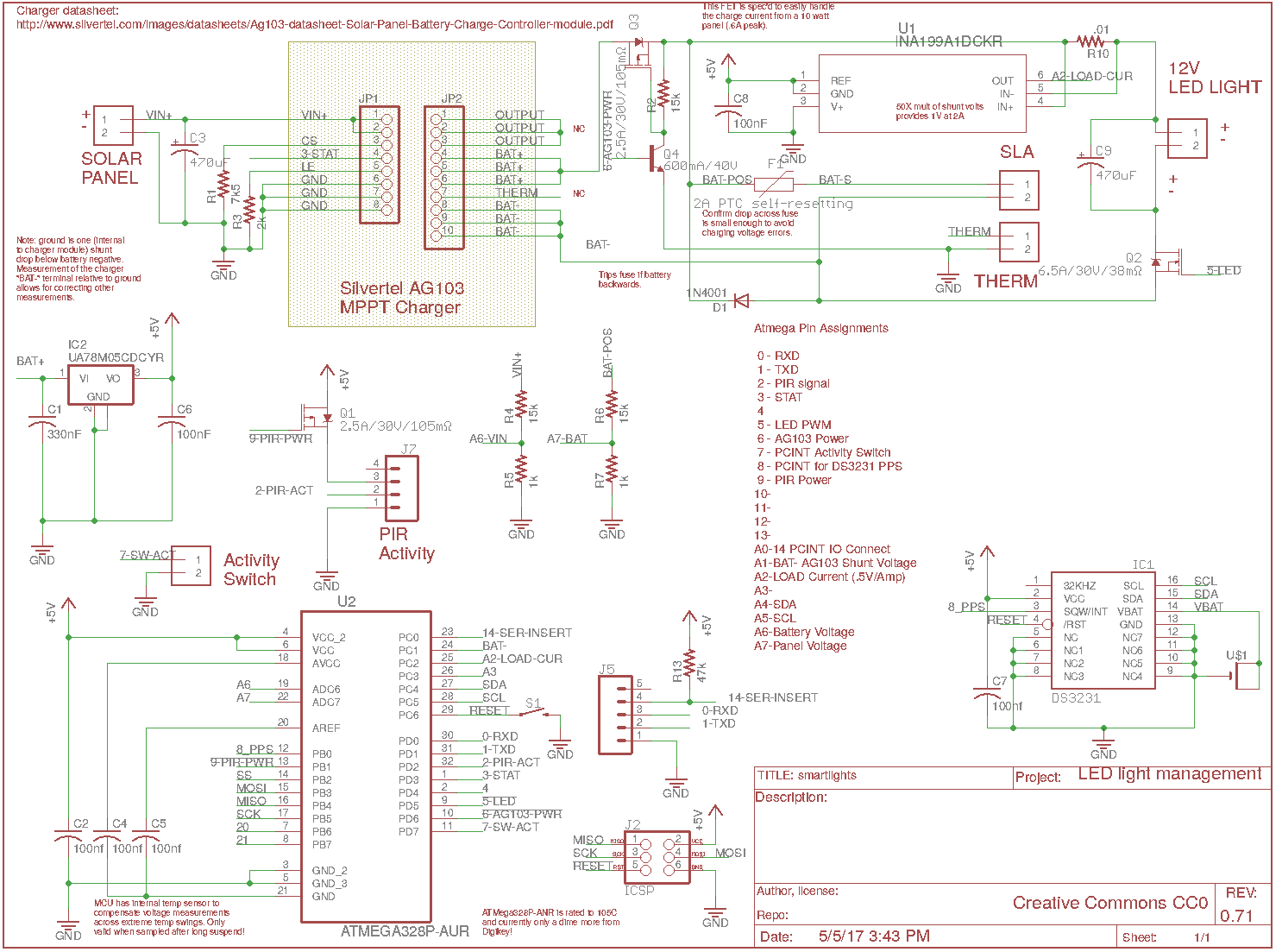
Although I'd been starting to use a custom MPPT circuit built around the LTC3652HV (and this is my fall back), I decided to try out an off the shelf solution in the form of a Silvertel AG103 "MPPT" sealed lead acid (SLA) battery charger. Together with a seven amp hour (7Ah) SLA and some custom electronics using an Atmega 328P MCU I expect to have a solution that works well for the little library as well as giving me a well instrumented platform for other applications.
Pete Soper, May, 2017
Initial charger circuit testing
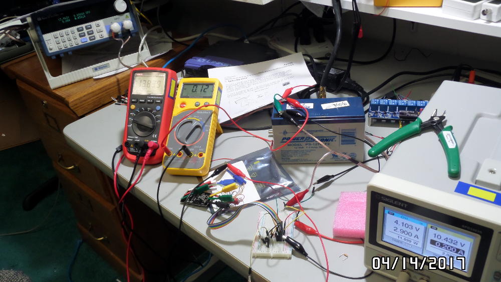
First impressions of the Silvertel ag103 charger (little board near corner of yellow meter) were good (but didn't hold up, as shown in later sections). The PCB is well made, choice of MCU is great (ST STM32 series in a nice TSSOP20 package). The whole thing is on a roughly 30x50mm board with two male headers the right length to solder onto a main board. The current plan is to neatly solder to the header pins while confirming this charger is going to get the job done and then move it to a permanent home on a PCB that has the rest of the circuitry.
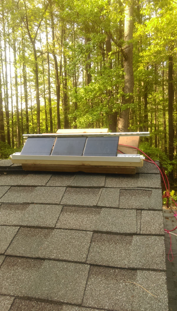
The initial target panel was going to be a Coleman unit rated at 2 1/2 watts, but this was judged inadequate. While determining this and shopping for a target panel three low voltage panels at hand were combined in series and mounted on the roof above my shop for testing.
So the system controller described later will be a carrier for the charger "daughter board", with the charger on the "back side" and the rest of the components on the front side of the board.
Thermal image of charger board passing a couple watts to battery while it drives an eight watt load" about 20F (11C) rise over ambient temperature
During later testing the load being driven by the charger board was increased to the target 13 watt level (the power that will be used by the LEDs at full brightness). A terrible "burned resistor smell" resulted. Then at even much lower power the load switch MOSFET was overheating terribly, such as here while driving a load of around an ampere (91C):
The voltage drop across the MOSFET was terrible: five volts, which translates to five watts being dissipated by the chip, which is a few times it's absolute limit. Replacing the (4407A) MOSFET with an equivalent (IRF9310) didn't change the behavior: something is causing it to be parked in its linear region instead of switching on fully or otherwise achieving a low Rds.
After a very brief urge to smash this board on a brick with a hammer I realized it's a non-issue. The battery can be used directly with the second PWM-driven MOSFET required anyway for brightness control. The only advantage would have been the charger disconnecting the LEDs if the battery voltage got too low. Except I have to implement that anyway because the cutout voltage is way, way too low. It's 10.5 for the Silvertel charger, but I insist on disconnecting the battery at a much higher voltage when the battery still has substantial capacity left. This is a conscious policy because battery life will be severely shortened by the battery being chronically discharged too deeply.
At this point I'm cautious about buying another AG103 without understanding what part of the circuit failed and whether it's a design problem or if (hopefully) I accidentally broke it. This board specifically provides overload protection, so it's hard to see how I inadvertently hurt it. But I'll be "popping a stack" by returning to testing the Linear Tech LT3652HV for the next charger project.
Breadboard charger testing
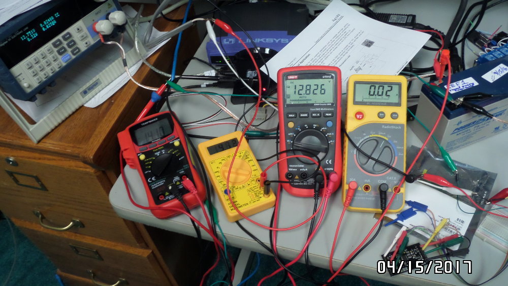
Here's the charger being driven by three little five volt panels in series (nearing sunset, but sun long since behind tall trees). From left to right is the Maynuo electronic load asking for a whopping 25mA, the red meter showing volts out of the panels, little yellow showing mA out of panels, propped up red showing battery voltage, and rightmost yellow meter showing amps in/out of the battery. Tomorrow about 11am when the sun gets fully over the trees there should be more action.
Test solar panels
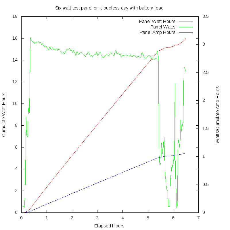
Three 5V, 2 watt panels in series. The AG13 "MPPT" charger settles to a load on these panels with around 15 volts output in full sun as shown by the graph below. (Power drops and comes back late in the day as the sun is blocked by tree limbs). Note that the angle of these panel was made much closer to flat after this shot was taken.
There is something very puzzling about this graph. One would think that panel output would show a peak as the sun came up and over to be closest to perpendicular to the panel and then fall as the panel was hit more obliquely later in the day. Why it's nearly flat, and even more puzzling, why there is a steady downward slope is a question I'd like to ask the AG103 designer. This and other collected data suggest the charger does not frequently update it's setting for maximum power from the panel.
Target Solar Panel
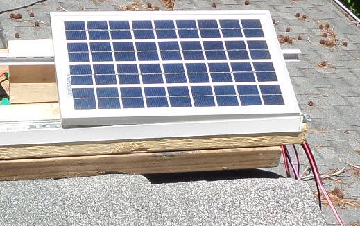
The photo above shows the target 10 watt panel on a roof top. For the Little Library it will most likely be mounted on a tamper-resistant bracket that fixes the azimuth but allows for adjustment of elevation a few times per year.
Specifications:
EcoWorthy 10w polycrystaline panel
- Voc - 20.6V
- Vop - 17.3V
- Isc - 0.69A
- Iop - 0.58A
- Output tolerance - +/-3%
- Temp coefficient of Isc (010+/-0.01)%/C
- Temp coefficient of Voc -(0.38 +/-0.01)%/C
- Temp coefficient of power Voc -0.47%/C
- Temperature range - -40c to +80C
- Guaranteed 90% output within 10yr, 80% within 25yr
- Low iron, high transparency tempered 3.2mm glass
- 337x207x18mm, four mounting holes: 168mm between centers on each of the long sides 178mm between centers across the panel
- 0.85kg 1.88lbs
Performance Data:
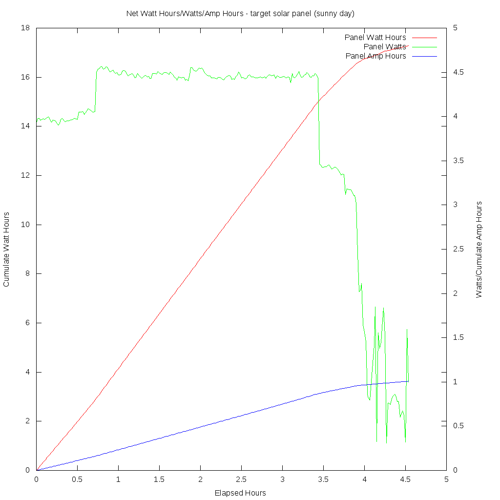
This graph shows the same panel on a sunny day. Output becomes erratic as the sun is blocked intermittently by a tall pine tree. The step changes in power output are disturbing. The 1/2 watt increase in output at the 3/4 hour mark and more than one watt drop at the 3 1/2 hour mark are hard to understand. It's as if the controller's policy is to establish a new maximum power point much less frequently than the actual rate of change as the panel reaches and leaves peak irradience. The algorithm for MPPT doesn't seem to be very good: certainly not as good as the "perturb and observe" strategy described in this Microchip white paper. But again, it's possible the controller's policy is simply not applied frequently enough. Still the idea of ignoring a good fraction of a watt hour because inappropriate conversion settings are held for long periods of time is annoying.
Rigol voltage/current measurement
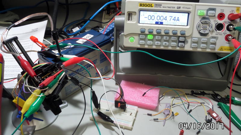
Here's a Rigol DMM measuring voltage and current every 60 seconds and putting measurements on the LAN for a simple python program can pick it up and log. This is after sunset and the charger board is drawing just a few mA out of the battery. The idle current is only 3-5mA in this case, beating the datasheet spec by a factor of two. But later samples showed long periods of idle current around eight milliamperes, and the datasheet limit is 10. Apparently there is a very high idle current in the low voltage supply for the MCU and associated circuits even when the MCU is sleeping (or they don't bother sleeping because it would make so little difference?) But this high idle current makes it obvious the entire MPPT board has to be powered up and down by my controller during night hours.
It should be noted here that unlike the charger (that uses DC-DC conversion with about 85% efficiency for getting it's power), the MCU and PIR (and any status LEDs, measurement resistor dividers, etc) need power at much lower voltage than the LED lights, so I have to drop the battery voltage down somehow. A simple linear regulator translates to a "seven volt dummy load". That is, if the PIR and MCU were to consume 10 mA while active then 70mW will be converted into heat by the regulator. An alternative supply circuit that is 85-95% efficient at low current levels is available if necessary. I'm torn between going with a simple linear supply while convinced the average current can be extremely low by virtue of the MCU being suspended most of the time anyway vs using a switcher or providing for the power supply choice to be delayed by making it a second daughter board.
And this raises another basic issue, which is the integrity of electrical connections in this system. The Little Library is an unprotected environment that will experience extreme heating/cooling cycles and condensing humidity. After meditating (fretting) about this for some time I've decided to design in screw type terminal blocks for the board, but leave these off and solder permanent connections to the board for the library. This will allow the board to be in out of the rain but positioned so fan air can be used if necessary for cooling, while the rest of the electronics (with prototyping connectors initially), by virtue of their very low power dissipation, can be in an air tight enclosure to avoid corrosion. Then actual experience with temperatures can guide whether the charger can be a soldered daughter board for the controller PCB as planned.
AG103 "MPPT" charger and target panel performance (the ACID TEST)
During a pefect, cloudless day a test of the AG103 MPPT performance was carried out by comparing it with manual setting of an electronic constant power load.
The test consisted of these four conditions in time order:
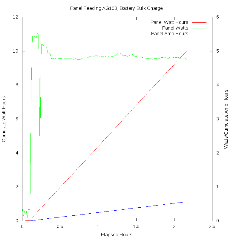
- "Condition 1" - 10w panel feeding the AG103 "MPPT" charger which in turn was feeding a 7Ah SLA that had had three amp hours taken out of it. That is, this battery was in need of a full bulk charge cycle. Also, a Mayhuo M9711 electronic load was drawing a constant 2/10 amperes from the battery. The intention being to make sure the charger didn't switch to float charge state.
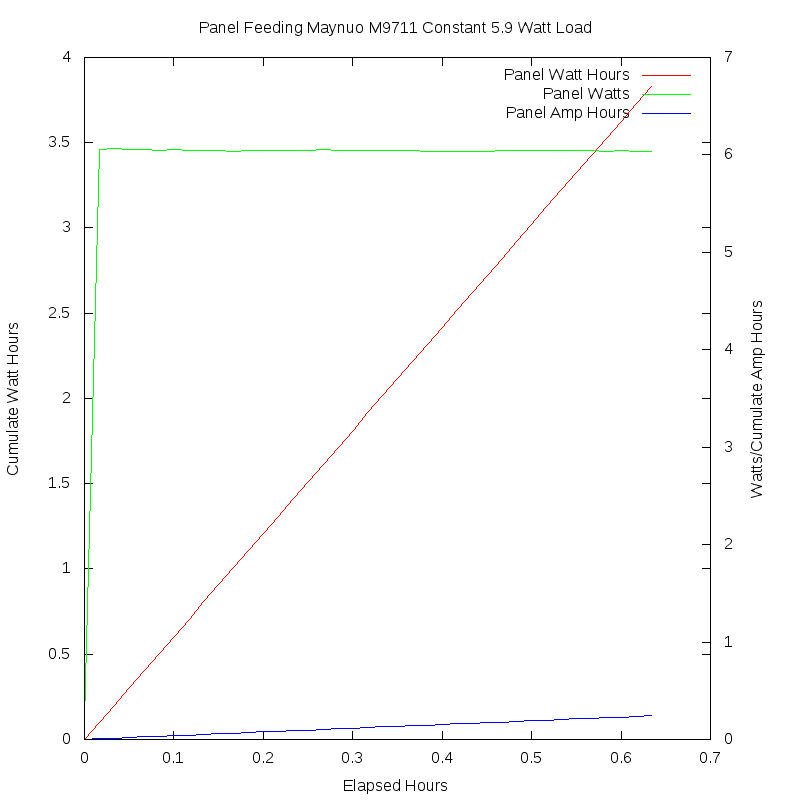
- "Condition 2" - 10w panel feeding a Maynuo M9711 Electronic load set to draw a constant 5.9 watts. No battery or other load attached. The Maynuo constantly changes the resistance seen by the panel so the product of panel voltage and current equals 5.9 watts.
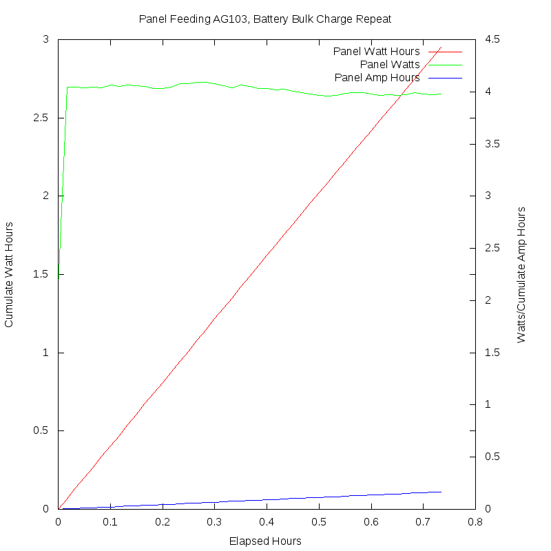
- "Condition 3" - 10w panel feeding the AG103 "MPPT" charger which in turn fed the battery, initially with no load, but then with the same .2A load. No panel output difference was noted with the load vs no-load condidtions here.
- "Condition 4" - 10w panel feeding the Maynuo M9711 set to draw a constant five watts. The panel would put out more than five, but the load was set conservatively to insure stable measurements for the last phase of testing.
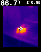
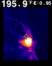
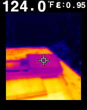
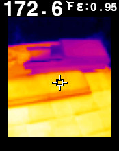
So the conditions were AG103 with everything arranged to signal to it that it should suck as much power out of the panel as possible, an electronic load pulling panel power, a repeat with the AG103, and a repeat with the electronic load. These were done sequentially on May 3rd, 2017 from 10:49am to 3:45pm EDT at latitude 36.7 degrees (near Raleigh, North Carolina in the USA). The elapsed times were 7801, 1261, 2641, and 1321 seconds respectively, with short gaps to switch equipment connections and settings. The ambient air temperature was around 24C, the roof under the panel was about 78C, and the panel surface was about 51C during the tests (see IR images below).
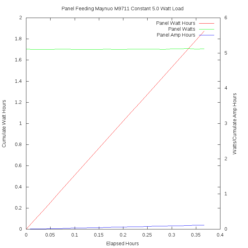
The red graph lines show the cumulative watt hours produced by the panel. Also graphed with green lines are the watts coming out of the panel and blue lines for the more familiar cumulative ampere hours. Note that the graphs show slightly higher power than the electronic load set points because of about a tenth volt drop in the test leads of the Rigol DM3068 DMM used for measuring current (the drop inside the DMM was about 10-15mV). But this drop was the same with the charger used instead of the electronic load. Also, slight variations in power shown in the graphs with the electronic load are artifacts of the fact that the voltage and current from the panel was varying rapidly and the current and voltage samples were taken a fraction of a second apart, so their product didn't always agree exactly with the actual power being delivered.
Here are the results:
This graph starts just before the panel had an unobscured view of the sun as it moved past the trees. This was followed by a big drop in power, a recovery, then a more gradual drop to what became the steady state power output of just under five watts. The raw data shows the panel voltage and current were around 17.2 and .32 respectively, then the panel voltage jumped to 19.9 with a current of .10 amps. Again, the current and voltage measurements are not concurrent (arranging this capability is high on my list!). However the subsequent sag in panel power from 5.2 to 4.8 watts involved 10 samples that don't show the spikes one would expect from badly mismatched measurements (e.g. catching the voltage at one level just as the charger is changing its impedance and causing the panel current to jump just before it too is measured). In any case, the takeaway is that the panel settled down and averaged about 4.7-4.8 watts until the switch to condition 2.
Say what?? With the electronic load the panel would put out over six watts. But the load had to be made conservative or it would turn itself off if the panel output collapsed from any change in panel conditions (there was a breeze that was perhaps dropping the panel temp a degree or two from time to time). So the load was set to draw 5.9 watts and the panel accommodated that with a very much lower voltage and much higher current than given to the AG103 just minutes earlier. This output stayed constant with slight changes in voltage and current for almost 40 minutes. Again, note that the graph shows closer to six watts because of measurement errors caused by test lead voltage drops.
The AG103 was reconnected, with care taken to disconnect/reconnect the battery too so the charger was sure to have been reset. The measurements were resumed about two seconds after reconnecting the panel and got initial samples of 18.9 volts and .113 amps or 2.1 watts. No conclusions should be drawn about the power as, again, there is around 1/2 second between the voltage and current samples. But the next sample 60 seconds later registered about four watts and this stayed close to constant for the roughly 3/4 hour measurement period. This was such a stunningly low power I just had to reverse conditions again.
This time I was torn between setting the electronic load to show (in a gloating fashion) maximum power vs risking the load turning itself off if the panel output collapsed, and it was well into the afternoon at this point. So I set it to a conservative five watts and the panel maintained this for the 22 minutes of the last part of the test. It doesn't take any higher math to note that the manually set load got 25% more power out of the panel than the AG103 got immediately before the last change of conditions. In the spirit of the "four pinocchios" the "Washington Post" awards many recent government pronouncements in this country, I award the Silvertel AG103 quotation marks for it's label. It is henceforth the AG103 "MPPT" Charger. If this turns out to be ambiguous "so called" will come next!
Some aspect of the change in the board causing the load pass transistor to be improperly switched might also account for the lousy maximum power point tracking. I wish I'd gotten two of these boards.
Here are images from a FLIR TG165 showing the temperature of the target solar panel and the roof it is sitting above on around the middle of the day of the test. The air temperature is about 24C. The two temperatures translate to 51 and 78 centigrade. The panel is resting mostly on two edges a few inches above a support made of a thick piece of wood.
